



How Do You Design a Mould Tool for Injection Moulding?
An injection mould tool is designed by translating the finished component requirements into a precise system of cavities, cores, feed channels, cooling circuits, vents and ejection features. The designer must account for polymer flow, shrinkage, draft, wall thickness, expected volume, machine capacity, cycle time, surface finish and maintenance. Tool design, and most importantly investment, should begin only after a design for manufacture review.
1. Define the component and production requirements
The toolmaker needs approved CAD data plus the polymer grade, tolerances, appearance standard, forecast quantities, expected tool life and required production rate. These inputs influence tool steel, cavity count, feed system and construction. Ambiguity at this stage can create expensive changes later.
2. Review the part for mouldability
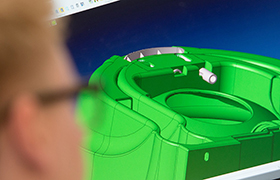
The component is checked for consistent wall thickness, adequate draft, practical radii, undercuts, shut-offs, likely shrinkage and ejection. The parting line and gate must be placed where they support filling without compromising visible or functional surfaces. Rutland Plastics’ injection moulding design guidelines and design for manufacture support address these decisions before tool manufacture.
3. Select the mould layout and cavity strategy
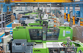
A single-cavity tool makes one part per cycle; a multi-cavity tool increases output but also raises tooling complexity and demands balanced filling. Family tools can produce different components together, although variations in size and flow can make control harder. The correct layout balances annual demand, cycle time, machine capacity and lifetime cost.
4. Design the runner, gate and venting system
The feed system must deliver molten polymer to each cavity at the correct pressure and temperature. Gate type and location influence filling pattern, knit lines, residual stress and gate witness. Vents allow displaced air and gases to escape. Mould-flow analysis can help evaluate alternatives before any steel is cut, but results still depend on accurate material and process inputs from an experienced designer.
5. Engineer cooling and temperature control
Cooling often accounts for a large share of the cycle, so channel position and balance affect both productivity and part quality. Uneven cooling can cause warpage, differential shrinkage and long cycles. Tool designers must work around inserts, cores, ejectors and structural requirements while keeping the cavity temperature sufficiently uniform.
6. Plan ejection, actions and automation
Ejector pins, sleeves, stripper plates or other mechanisms remove the cooled component without distortion or unacceptable marks. Slides, lifters and collapsible cores may create undercuts, while sensors and automation can support safe repeat production. Every moving feature adds cost and maintenance, so unnecessary complexity should be designed out.
7. Manufacture, trial and refine the tool
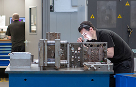
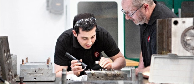
After detailed approval, the tool is machined, assembled and sampled. Trial parts are assessed for dimensions, appearance and function, and process data is reviewed. Adjustments may be needed before final sign-off. Rutland Plastics provides in-house injection mould tool services, trial moulding and ongoing maintenance within the same manufacturing relationship.
What makes a mould tool commercially successful?
A successful tool does more than make one acceptable sample. It must deliver stable parts at the planned cycle time, fit the intended machine, remain serviceable and support the required lifetime volume. Early collaboration between product designer, toolmaker and moulder is therefore essential. Rutland Plastics can provide all these services and coordinates this through project management process; speak to the Rutland Plastics team to review a tool requirement.
FAQs – Mould Tool Design and Product Quality
Timescales vary with component complexity, number of cavities, actions, analysis and approval requirements. Tool design is one stage within a longer manufacture, trial and validation programme.
It is the line where the main sections of the mould meet. Its position affects appearance, tool construction, venting and how the component is released.
Draft is a slight taper that helps the cooled component release from the tool without scuffing, excessive force or damage.
A cold runner solidifies and is ejected with the parts, while a hot runner keeps polymer molten within a heated feed system. The right option depends on material, volume, waste, maintenance and economics.
