DESIGN FOR MOULDABILITY (PART 2)
Here we shall look in more detail at adding strength by the addition of ribs. In particular how ribs and bosses should be designed for both performance and appearance.
Rib Guidelines
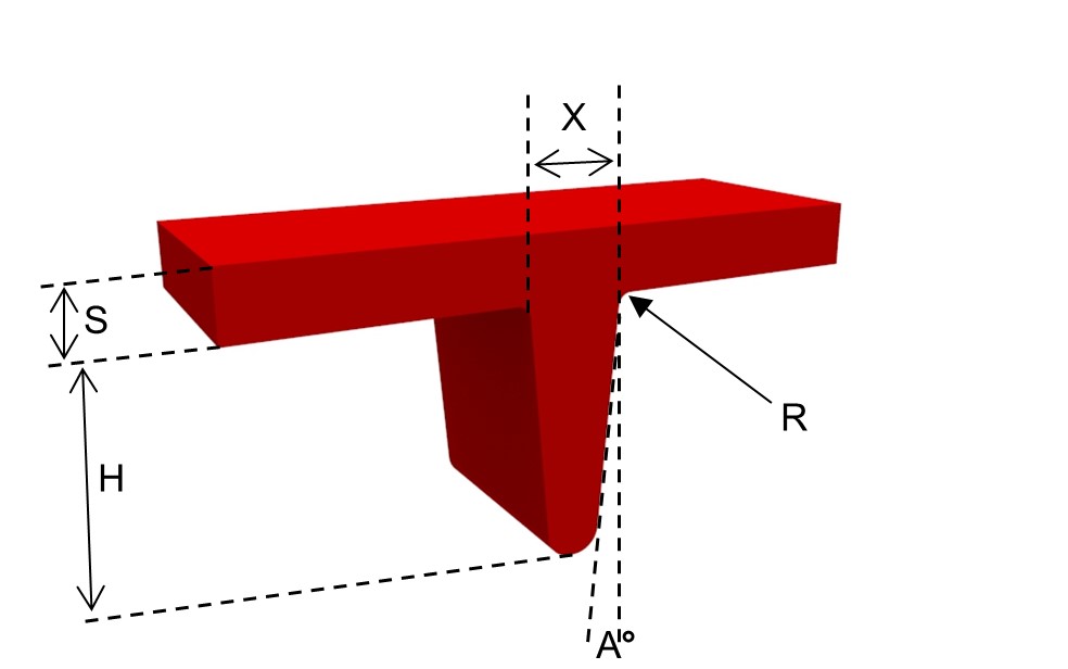
Component Section = S; Draft per Rib Side = A = 0.5 – 1.5 Deg; Rib Height = H = <5 x S (usually 2.5-3 x S);Radius = R = >0.25 x S – 0.4 x S; Rib Thickness = X = 0.4 x S – 0.8 x S; Rib Spacing = 2 x S – 3 x S
RIBS
Ribs can be used to increase the stiffness or strength of a component without increasing the overall wall thickness and so increasing the weight of the component. However, ribs can increase the risk of warping and appearance problems. For successful rib design the following guidelines should be followed:
- To reduce sink marks on the surface the rib thickness should not exceed 50% of the adjoining wall thickness
- To reduce stress, filling and ejection problems the height of the ribs should not exceed three times the adjoining wall thickness. When more strength is required more ribs are recommended rather than an increased height. A deeper rib may buckle under load plus it is difficult to machine into the mould and may cause the part to stick in the mould
- A minimum radius of 25% of the adjoining wall thickness should be incorporated at the base of the ribs
- Ribs are most effective when placed down the length of the area subjected to bending
- Rib spacing should be at least twice the nominal wall thickness
- A draft angle of at least 0.5 degrees on each side should be incorporated in order to facilitate release from the mould
SUPPORT RIBS
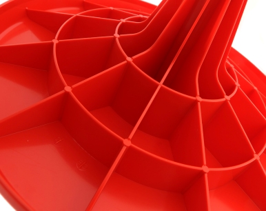
Support ribs may be used as reinforcement for corners, side walls or bosses. The following guidelines should be adhered to wherever possible:
- Thickness should be between 50% and 70% of component wall thickness
- Minimum distance between faces of ribs should be twice component wall thickness
- Minimum length of support rib face attached to component wall should be twice wall thickness
- Generous radii should be incorporated at rib ends
- Minimum of 0.5 degree draft should be incorporated
- Minimum length of support rib face attached to a boss should be four times wall thickness
BOSSES
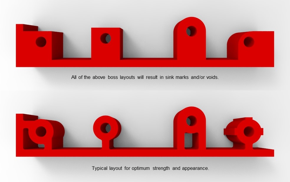
Bosses are usually incorporated to facilitate mechanical assembly. They can be designed to accommodate self-tapping screws, push-in or moulded-in inserts or used for ultrasonic welding. Therefore, the boss may have to withstand a variety of forces – tension, torsion, compression, shear and flexing.
Design suggestions:
- Wall thickness of the boss should be 50% to 70% of the nominal wall. However, this may not be sufficient to withstand the stresses imposed by an insert but a thicker section can cause sink marks. Frequently, a compromise is required.
- Minimum radius of 25% of the wall thickness at the base of the boss is recommended.
- Further strength may be achieved through the use of support ribs.
- Strength can also be increased by attaching the boss to a nearby wall using a rib.
UNDERCUTS
Undercuts should be avoided if at all possible. Ideally mould tools should be straight open and close. In certain circumstances mouldings with slight undercuts can be ‘bumped’ off the core. The same results as an undercut can be achieved using certain design techniques. For some complex components, it may still be necessary to have side movements in the mould tool but it has to be accepted that this will increase tooling costs.
There are various alternative solutions that Rutland Plastics would be happy to discuss and advise on.
FURTHER READING OR LINKS TO ALL GUIDES?
- Design Guide
- Design Development
- Design For Appearance
- Design For Assembly 1
- Design For Assembly 2
- Design For Assembly 3
- Design For Cost Consideration
- Design For Economy
- Design For Mouldability 1
- Design For Mouldability 2
- Design For Mouldability 3
- Design For Precision
- Design For Recyclability
- Design For Stiffness
- Design For Strength
- Design For Time
- Design Summary
- Flame Retardancy
- Flexibility
Free design guide

"*" indicates required fields

